

The building boom of recent decades, together with massive advances in technology and materials have led to increased demands on the machines used to manufacture construction elements and assemblies. As well as robust construction, efficiency and reliability are more important than ever.
HAGE has supplied high-tech solutions for leading manufacturers in the building industry ever since the company was founded. These include individual machines for fabricating formwork elements or floor props, as well as machines for 6-sided processing of wood. HAGE finds the best complete solution for every customer.


MACHINING CENTRE
FOR WINDOW PROFILES
Developed for the fully automatic production of window profiles, the new system machines up to 500 different profile types. The system is divided into two machining centres with automatic tool change and a sawing station.

System components:
- Flat magazine
- Infeed roller table
- Profile check
- 5 NC feed clamps
- Machining centre 1 with 8 spindles Double-angle saw for mitre, straight and shifter cuts
- Machining centre 2 with 5-axis machining head and automated tool change
- NC profile clamping device
- Automatic chip removal
- Outfeed roller table
- Outfeed buffer
The workpieces are fed in manually by the system operator. At the end of the infeed conveyor, the length, width and height of the profiles are measured before they are aligned and prepared for further transport. The system uses the measurements to identify the profile type, and selects the requisite work steps. Five 4-axis NC feed clamps transport the profiles through the system,
The first machining centre is fitted with eight spindles. At the following station, the 5-axis saw makes straight, mitre or shifter cuts. Front machining of the profiles is carried out by a 5-axis swivel head in the second machining centre. The profile is drilled, milled or sawn, depending on the workpiece. The tools are changed automatically by the integrated 40-way tool changer. Chips or cuttings are automatically removed and separated by type. A section gripper transports the completed window profiles to the outfeed buffer, from where the operator removes them.


FSW machine
for floor elements
In this application, the HAGE FSW Light Use processing centre is used for longitudinal welding of aluminium extrusion profiles.
The FSW processing centre has two workstations which the machine works on alternately. The individual sections are loaded into the semiautomatic clamping system by hand. They are then welded together by FSW with two welding heads, with an automatic joint detection function. A roller moving along the joints ahead of the welding head presses the workpieces down and another roller follows the welding head and flattens the surface of the metal. Both rollers are controlled via integrated pressure sensors.
LINE COMPONENTS:
- Machine base with X-axis for two workstations (alternating processing)
- Gantry design calculated by FEM
- Clamping systems
- Two FSW heads
- Pressure rollers for holding and smoothing the workpiece
- Code stamping station applies product ID
- Safety equipment
- Process monitoring by HAGE FSW WeldCheck
SAWING & PUNCHING LINE
The vertically integrated production of this system comprises the end-to-end production of steel door frames - from cutting the raw material to size through the various machining processes (punching, embossing, component testing etc.) all the way to presentation of components to the next section of the system.


LINE COMPONENTS:
- Feed conveyor with automatic manipulator to destack the parts
- Buffer conveyor with part turner
- Feed roller conveyor
- NC cutting station with 2 NC transport grippers
- Conveyor for waste from cutting & punching
- Disposal of waste lengths of material
- Parts handling/conveyor system to the punching station
- 2 NC feed grippers with length measurement
- Punching station with 14 NC punching units
- 180° part turner
- 3 buffer conveyors
- Safety equipment
- Oil mist extraction system
In subsequent steps the parts are measured, punched, and following a Q check, transferred in pairs to defined buffer conveyors, which bring them to the welding station.
These steel U-bars are used as frames for girder wall formwork and a variety of special applications.


SPECIAL
FRAME SAW
Special frame saw for the automatic machining of various steel frames The product range includes basic and supplementary frames in standard and, above all, special designs, such as those used for renovations or retrofitting.
The tubular section frames are placed in the inlet buffer station manually by the system operator and are then segregated and indexed for further machining. The frames are picked up individually and aligned precisely by the infeed roller conveyor. A feed gripper then takes charge of further transport to the sawing centre. This is equipped with two HAGE sawing devices with impressively precise double mitre cuts, long service life of the saw blades and the HAGE Cut high-performance saw gearbox. For the saw cutting operation, these frames, some measuring up to 540 mm in width, are clamped accurately by several servo-controlled clamping elements on all surfaces and edges. Next, the finished frame components are removed from the saw centre by a second feed gripper and are then labelled. After that, on the outlet buffer, the frames are conveyed out of the system and are then removed by the operator. Offcuts or excess lengths are conveyed away automatically. The system obtains the order data needed for this process from a direct communication interface linked to a higher-level control system.
Technical data:
- Machine precision: +/- 0.1 mm | +/- 0.025°
- Axis speeds: up to 3 m/s
- 23 servo axes
- HAGE Cut high-performance saw gearboxes
- Mitre angle: +/- 45°
- Sawblade diameter: up to 500 mm
- Intelligent clamping fixture
punching line for
steel u-bars
Steel U-bar sections up to 12 m long are loaded into the feed line, automatically unstacked, if necessary turned over and then cut to lengths of 720–6,000 mm.


LINE COMPONENTS:
- Feed conveyor with automatic manipulator to destack the parts
- Buffer conveyor with part turner
- Feed roller conveyor
- NC cutting station with 2 NC transport grippers
- Conveyor for waste from cutting & punching
- Disposal of waste lengths of material
- Parts handling/conveyor system to the punching station
- 2 NC feed grippers with length measurement
- Punching station with 14 NC punching units
- 180° part turner
- 3 buffer conveyors
- Safety equipment
- Oil mist extraction system
In subsequent steps the parts are measured, punched, and following a Q check, transferred in pairs to defined buffer conveyors, which bring them to the welding station.
These steel U-bars are used as frames for girder wall formwork and a variety of special applications.


Production line for
scaffolding poles
The raw material bundles with tubular sections measuring six to 12.5 m in length are deposited in a separating magazine. From there, the tubular sections are directed to the sawing machine where raw materials are cut to final workpiece lengths of 460 mm to 3 m. Other preparatory steps are taken before the machining stations: Deburring brushes on the ends of the tubular sections, blowing swarf out of them and an automatic length check. The weld seam detection station determines the position of the longitudinal weld seam in the tubular sections, ensuring that they are always passed on in the correct position to the various machining stations. After various punching operations, the ends of these tubular sections are shaped (constrictions and end stamping) and an adapter journal is fitted.
Finally, all the punching operations performed are checked at a test station before the poles are finally stacked on stanchion pallets.
Technical data:
System size: approx. 20 x 22 m
Initial lengths: 6,000 - 12,500 mm
Long finished parts: 460 - 3,000 mm
- Soundproof booth above the system
- Vertically integrated production: entire production process from sawing of raw material to various machining processes including comprehensive quality control up until the finished parts are stacked and stored
- 21 different types of part
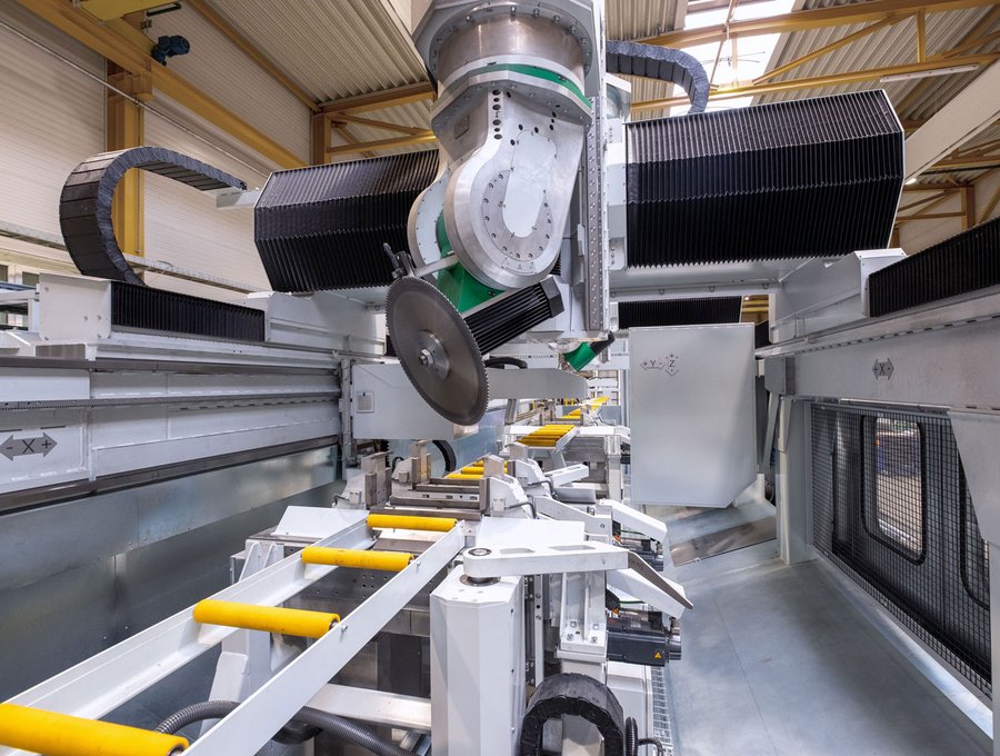
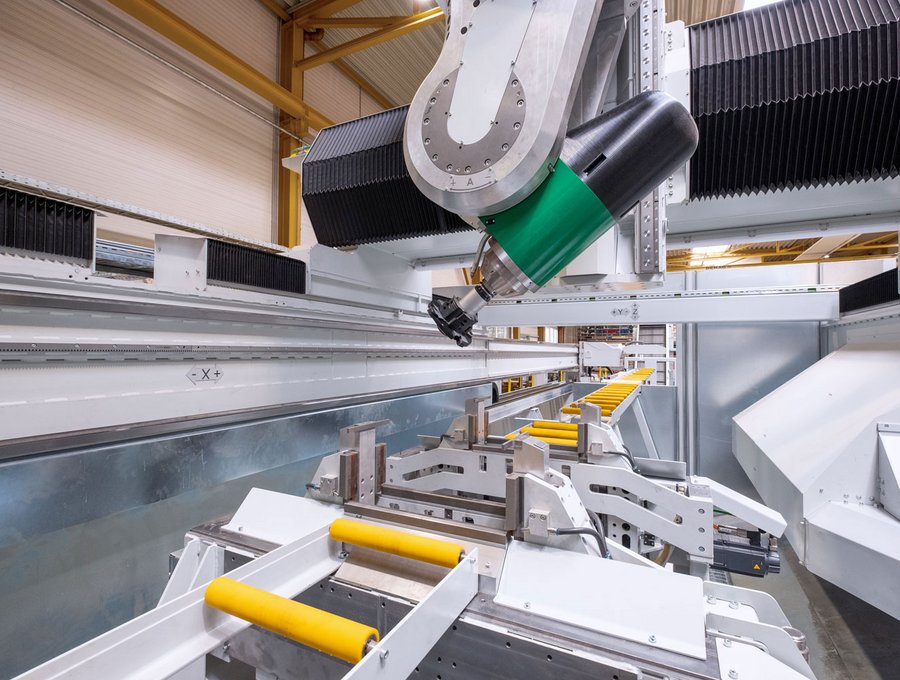
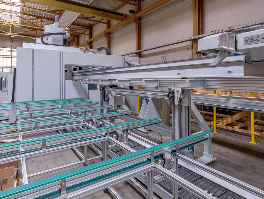
Automatic CNC timber
processing centre
The precise, 5-axis CNC timber processing centre cuts and shapes natural and laminated wooden parts and beams of up to 20 m in length.


TECHNICAL DATA:
Working envelope
Length: approx. 20,000 mm
Width: approx. 1,600 mm
Height: approx. 700 mm
Range of travel
Length (X) of workpiece carriage: approx 40,000 mm
Width (Y): approx 2,800 mm
Height (Z): approx. 1,800 mm
- 6-sided processing without angle heads, 5-axis transformation (interpolating axes)
- HSK 63 A spindle with 18,000 rpm speed, 30 kW power
- Access to the spindle from all sides
- State-of-the-art CNC control
- Standard tool changer with 20 positions, special tool changer with 4 positions
- Workpiece weight max. 9 t using 6 workpiece carriages
It provides 6-sided processing without using angle heads, without unclamping and reclamping the workpiece – and without reducing power delivered by the spindle.
The laminated timber parts clamped on the workpiece carriage are presented to the column-type router to a precision of one-tenth of a millimetre. A two-axis routing head is carried on a Y-beam projecting from the machine stand. There is a fully automatic tool changer for 24 tools. The machine operator works from a soundproof cabin with full-length windows that give an unhindered view of the process.